
Why include a page on electricity? All hardware and equipment are powered by electricity, yet few know even the basics of electrical power. This is a brief primer to introduce you to the most basic electrical concepts.
The majority of equipment residing in the provider’s POP’s, run on 48 volts DC power. Most vendors sell 120 volts AC to 48 volts DC converters in power modules (cards) with their equipment. These converters are only required at customer sites, where the only available power is 120 VAC.
Huge UPS systems consist of intelligent backup batteries and gasoline powered generators to ensure no interruptions occur at all IXC POP’s and LEC CO’s. You may never be involved in the design or troubleshooting of electrical systems – but as a Telecom professional, it would be helpful to understand the basics of how electricity works.
AC vs. DC
There are two types of electricity, AC (Alternating Current) and DC (Direct Current). Power to facilities is always supplied as AC because AC power can travel long distances (so long as high voltages are used) with very little power loss. DC power is subject to a great deal of power loss over long distances and also is susceptible to noise interference from the ambient electrical disturbances in the atmosphere.
AC power is immediately converted to 48 VDC at the IXC facilities since all equipment runs on DC. The equipment with no DC input and instead is plugged into an AC outlet has internal circuitry that immediately converts DC power, although not necessarily at a 48-volt level. For example, computers plug into 120 VAC outlets and then convert this into 12 or 5 volts (for the cooling fans and hard drives) and 3.3 volts for the Motherboard and expansion cards (sound card, video card, etc.) circuitry.
Suggested Reading:
![]()
Voltage, Current, Resistance, and Power
The perfect analogy to electricity is water flowing through a hose. Electrons are like water – they are atomic-sized units that flow through a metal wire. A wire is like a hose – it is a metal conduit for the current to flow through.
- Current (I) is like the flow of the water – the more the current, the faster the flow of electrons.
- Voltage (E) is like the water pressure – the greater the voltage, the more pressure there is.
- Resistance (R) is like a crimp in the hose – the more resistance, the less current that can flow.
- Power (P) is the product of voltage and current (the water pressure x the rate of water flow).
There are but two formulas that represent the relationship between these four quantities. The formulas are called “Ohm’s Law“:

The Ohm’s law “pie” is the easiest way to remember the relationship between Voltage (E), current (I), and Resistance (R). Just remove one, and the two that are left show you the equation. For example, remove the I, and you are left with E/R, and therefore, I = E/R. So, the three equations from this are:
E = IR I=E/R R=E/I
![]()
Power
P = EI (and from that, we can deduce that E=P/I and I=P/E).
E is measured in volts, I is measured in Amps, R is measured in ohms, and P is measured in Watts.
For example, a 75 watt light bulb runs on our household AC power outlet, which is 120 volts AC. Therefore, the current running through the filament in the bulb can be calculated as:
I = P/E = 75/120 =.625 Amps
![]()
Using Ohm’s Law to Design a Circuit Breaker
For example, a 120 volt AC router rated at 18 watts will draw the following amount of current:
I = P/E = 120/18 = 6.7 amps
All equipment draws less and more current periodically, so you need to leave a margin for these regular surges. You do not want the circuit breaker to be constantly tripping. For this example, you could protect the router from a considerable surge with a 10 Amp circuit breaker or fuse.
![]()
Resistance
Resistance is simply a measure, in “ohms” of how much a material “resists” the flow of current (rate of the flow of electricity, in “Amps“) at a given voltage (electrical pressure in “Volts“). Metal has almost no resistance, and for short wires is considered zero ohms. Long wires or cables present a measurable resistance.
A “resistor” is a tiny cylinder used for mounted circuit boards, which has been manufactured to give an exact, preset amount of resistance to electrical flow.
Everything has resistance. Wood, glass, plastic, and rubber have an incredibly high amount of resistance. In contrast, water has a low resistance (hence the caution about never standing in water when dealing with electrical power). This is why the rubber is used as an “insulator” outside of cables – to protect people from accidental shock.
Resistance may seem like an undesirable quantity. However, it is crucial in controlling circuitry because it can lower a voltage down to the desired level. For example, a radio’s final amplifier transistors may require 12 volts, but the primary source is 24 volts. By combining a couple of “resistor” in series with the 24 volts, a 12-volt source is created.
![]()
DC (Direct Current)
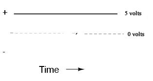
Direct Current travels in one direction. Although electrons from a lower voltage to a higher voltage – current, by tradition, flows from Positive to Negative or from a higher voltage to a lower voltage. Therefore, if you apply 5 volts to one end of a wire and 10 volts to the other end – this creates a differential of 5 volts, and the current will flow from the 10-volt end to the 5-volt end. If you apply 6 volts to one end of the wire and ground the other end (0 volts) – the current will flow from the +6 volt end to the 0-volt end.
This is what happens in a typical large flashlight. There are four 1.5 volt batteries in series for 6 volts on the positive (+) end and zero volts on the negative (-) end. The two ends of the batteries are connected to the light bulb, and the current flows from the +6 volt end, through the bulb and its filament, and back into the 0-volt end.
NOTE: “Ground” is always zero volts
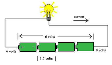
All CPE equipment runs on DC, even though it plugs into the AC outlet. As soon as the AC electricity enters the unit, it is converted to DC.
![]()
AC (Alternating Current)
When Edison first invented the electric light bulb, it ran on DC power. Subsequently, the first towns to have electric lights in their streets used DC power. The problem was that DC power is very inefficient when traveling over long distances. It is also very sensitive to noise in the lines.
Standard Alternating Current flows in one direction, slows down, and then reverses its flow in the other direction – back and forth, back and forth, 60 times per second (60 Hertz). Not only has this proven to be very efficient, but it can also be created very quickly by rotating generators. It was found that by using high voltages across the power lines, the distance problem could be solved, and at the consumer end, the voltage is “stepped down“:
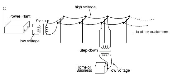
When a coil of wire moves across a magnetic field, electrical current is produced, and the same thing happens when a magnet is moved across a coil of wires. However, with a generator, the magnet’s movement is circular, which causes the current in the coils of wire to move in one direction for the first 180 degrees of rotation and then in the opposite direction during the final 180 degrees of rotation. It “alternates“. In reality, it is the “voltage” that alternates and travels down the power lines. There will be alternating current if a device is turned on. Still, regardless of whether any devices are turned on and begin drawing current – there is always an alternating voltage (electrical “pressure“) present. This is why at any time you can flip a switch and turn a device on, and it will instantly begin drawing power and working because the voltage is always there.
The 120 volts AC alternating voltage from the Power company present in your wall sockets do not instantly go from zero to 120 volts. Instead, it starts out at zero, builds up to a peak of 170 volts, reduces back down to zero, builds up to a peak of negative 170 volts, and goes back to zero. This “cycle” is repeated 60 times per second. This 60 cycle is the “hum” you hear from a generator. If you chart this signal of voltage over time, you get what is called a “sine” wave, which repeats forever:
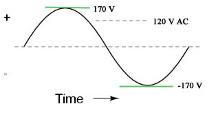
The 170 volts is the peak voltage, and the 120 volts is called the RMS (Root Mean Squared) voltage. This can be thought of as the average voltage, and that is why your home power is rated at 120 volts instead of 170, as it is the average amount present.
![]()
AC to DC Conversion
When the 120 volts AC (120 VAC) enters a CPE piece such as a router, an electronic device called a “bridge rectifier” converts the signal to DC – it simply reverses the negative portions of the sine wave into positive signals. The resulting waveform looks like a series of camelbacks.
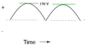
A large capacitor and other circuitry “filters“, or smooths out the signal to a stable, constant DC level of voltage – the same as what a battery would provide. The voltage can be controlled by the filter circuitry, and just about any level can be obtained. For computers, 12 and 5 volts are common values.
![]()
*** Excellent detailed, easy-to-follow guides are available at http://www.electronics-tutorials.com/


