


Note: These symbols are used in “schematics“, which are diagrams of electronic circuits. Other standard components, not shown or discussed here, include diodes, transistors, and IC chips.
Electronics is actually a branch of physics. It deals with the emission, behavior, and effects of electrons (as in electron tubes and transistors) and electronic devices or equipment. But to most people, electronics are just parts mounted on a circuit board that works together to perform some task, such as a radio receiver.
Electronics can be described as circuits, comprised of interconnected components, that use electricity as their “fuel“. As we all know, those circuits can do incredible things!
Resistors
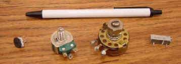
Resistors are the simplest of all electronic devices. They are small cylindrical components manufactured to have a specific amount of resistance, measured in “ohms“. The symbol for ohms is the Greek “omega” symbol:
Variable resistors that can be adjusted manually are called “potentiometers“, those that vary their resistance based on applied voltage are called “varistors“, and those that vary based on temperature are called “thermistors“.
Ohm’s Law applies to all resistors:
Remember that “E” = “V” = voltage. The Ohm’s law “pie” is the easiest way to remember the relationship between Voltage (E), current (I), and Resistance (R). Just remove one, and the two that are left show you the equation. For example, remove the I, and you are left with E/R, and therefore, I = E/R. So the three equations from this are:
E = IR I=E/R R=E/I
![]()
Power
P = EI (and from that, we can deduce that E=P/I and I=P/E).
E is measured in volts, I is measured in Amps, R is measured in ohms, and P is measured in Watts.
Calculating current through a resistor – as shown below, the voltage, “E” is 10v, and the resistance, “R” is 5 ohms.
Therefore: I = E/R = 10/5 = 2 A (2 amps)
![]()
Series and Parallel Resistors
If we want to calculate the currents:
- Serial circuit: I = E/R = 9/18000 =.5 mA.
- Parallel Circuit: I = E/R = 9/625 = 14.4 mA.
![]()
Capacitors and Inductors
The 3 most common electronic components are Resistors, Capacitors, and Inductors. As mentioned, a “resistor” is a tiny cylinder used for mounted circuit boards, which has been manufactured to give an exact, preset amount of resistance to electrical flow.
Capacitors store electrical energy, and Inductors store magnetic energy. They are the inverse of one another.
- the amount of capacitance is called “C” and is measured in “Farads“.
- the amount of inductance is called “L” and is measured in “Henries“.
Both capacitors and inductors can filter frequencies. There are many ways of connecting them together and filtering out only specific frequency ranges. This type of simple circuit is often referred to as an “LC” filter (L = Inductance measured in mH (milli-Henries), and C = capacitance measure in uF (micro-Farads)). If they reject one band of frequencies and allow another to pass – it is called a “bandpass” filter. If they are configured to block a band of frequencies in the middle of the range, it is called a “notch” filter.
H3|Capacitors and Capacitance
Basically, a capacitor is like a battery in that it stores electrical energy. In fact, capacitors are made from two plates that store a charge, just as batteries are. However, most capacitors store much less electrical energy (power) than a battery, and they won’t hold a charge for long. The amount of energy that a capacitor can store is measured in “Farads” (usually, you will see them rated in uF, which is “micro-farads“).
“Stray“, or “Extraneous” Capacitance – the reason that two wires (such as the twisted pair telephone wires) have capacitance is that the two wires act as two plates in a capacitor. The amount of capacitance is minimal but creates a problem nevertheless. There are no actual physical “capacitors” on the line – however, “extraneous capacitance” does exist, and just as it does on any line, it has the effect of reducing voltage variations – it “smooths out” the signal. This makes the voice sound muffled, and it loses its higher frequency range in particular.
A capacitor’s typical usage is to smooth our voltage levels on a line for power supplies or act as a frequency filter on circuit boards. Allowing low frequencies to pass but blocking high frequencies. This is fine for power supplies, where you want a constant voltage. But with voice circuits for telecom, you want the original signal to arrive intact, as close to the originally transmitted signal as possible. You need to retain the high frequencies. Therefore, load coils (inductors) are placed in series with the line to negate the stray capacitance.
![]()
Inductors and Inductance
Inductance is the opposite of capacitance – it occurs in tiny amounts in a straight wire. It can be significantly amplified by coiling the wire. An Inductor is simply a coil of wire, and inductance is the relative amount of resistance to current changes. Inductance is measured in “Henries” (usually mH, which is “milli-henries“). It is like an electrical “flywheel” which stores “magnetic energy“, and when low-frequency signals go through an inductor, they are filtered out. , and it has two main electrical/magnetic properties:
- When current flows through an inductor by placing a voltage across the two ends of the wire – an invisible magnetic field is created. The old lab exercise proves this, where you wind a wire around a nail, connect the two ends to a battery. Then the nail becomes a magnet until the battery is disconnected.
- When a magnetic field passes across a coil that has no voltage or current applied to it – electrical energy is created, voltage builds up, and current flows out of the inductor.
When voltage is applied to an inductor, current flows through a coil, building up an invisible magnetic field. The resulting magnetic field is like a flywheel – it resists change, and therefore fluctuations in current are resisted. The higher the frequency of current change, the more resistance to it. Also, the more turns on the coil, the more inductance it has.
NOTE: if the current is flowing through an inductor, and then suddenly it is shut off – this causes the magnetic field to come crashing down, which. … if the circuit is open and there is no way for current to be dissipated. The field crash causes a huge voltage to occur – and this is the way car distributors create sparks across the gap in the spark plugs.
The higher the frequency, the more resistance it encounters.
![]()
Series and Parallel Capacitors

![]()
Series and Parallel Inductors

![]()
Lessons in Electric Circuits” – excellent detailed, easy-to-follow guides – download them from http://www.faqs.org/docs/electric/ Also, see http://www.electronics-tutorials.com
![]()


